|
Level 2, Version 1.1
0. Introduction 1. Connecting the board
2. Powering up the system
3. Telescope Motion Control 4. The Menu
5. Using Planetarium Software 6. Troubleshooting
0. Introduction
Congratulations! Your new Gemini telescope control system has been designed to help you to make maximum use of your precious observing time. It is more than just a pointing aid. You can use it for preparing your observations, looking up objects in its databases or calculating their height and hour angle at a given time and location in order to plan photo sessions. You can use the Gemini as a completely standalone system in the field. If you decide to control it from a PC with your favorite planetarium software, it will follow the commands over the serial connection in real-time. There are lots of features
designed to help you. You may need some time to make full use of them.
Although most should be intuitive, carefully reading this manual will shorten
your learning curve. But even for a quick start, you should at least read
Chapter 2, "Powering up the system" !
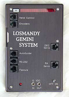
1. Installing the hardware and Connecting the board 1.0 The Hardware The Gemini servo drive system is available as a fully backwards compatible kit, or pre-installed at the factory. For kit users, the new Servo drive motors that come with your Gemini system have been designed to use the same bolt hole patterns as the earlier Hurst stepper motors used on all earlier Losmandy mounts. You will however require a small hex key, and possibly a pair of pliers to remove the existing bolts or threaded posts (depending on the model of mount being upgraded) that hold the original motors onto the mount. Simply substitute the new DC servo motor for the Hurst stepper motors. The Gemini main electronics panel also has the same width and bolt hole patterns as the earlier stepper electronics, and can be easily installed on the same location after the stepper electronics have been removed. 1.1 Hand Controller (HC)
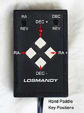
The HC plugs into the socket at the top of the left side. The HC works in Telescope Control or in Menu mode. Toggle between these two modes by depressing the little illuminated key on the upper left side of the board. With the HC positioned so that the cable is on the bottom, set the two upper switches to RA and DEC (not REV). The upper diamond button will now be DEC+, the lower will be DEC-, the right button will be RA+ and the left one will be RA-. In fact, the RA keys should be called HA (from Hour Angle) and the DEC direction changes at the poles, but this is the way most have become accustomed to. If you are using the original Losmandy hand controller, soldering of a capacitor of about 4.7nF over each of the 4 HC keys is necessary. 1.2 Encoder Plug into the 8-pin socket
below the HC input. The layout is compatible to the Y-cable of the usual
DSCs, like the Losmandy DSC or the NGC Max. The encoder ratios and directions
can be defined in the Menu item Setup->Encoder (see below). The default
setting is -4096 for both axes, as used for the G-11 mount. The sign indicates
if the encoder is moved in the same or the opposite direction in relation
to the axis it is connected to. The system does not require shaft encoders
to be fully functional. Connected to the servo motors are motor axis encoders
for measurement of the motor axis position, giving about 0.5 arc second
accuracy. For comparison, the accuracy of the 4096 tick/rev axis encoders
is about 5.27 arc minutes. Refer to the table below for other Losmandy
mount encoder settings.
Connecting shaft encoders has some advantages. The system will keep track of the telescope?s position even when you are moving the OTA manually. Without encoders, you mustn't move in RA manually, not even for searching an alignment star. The reason for this is simple. The system must know where the eastern and western limits are and when it has to make a meridian flip. With encoders, the system is informed about manual movements and can take them into account, thereby avoiding exceeding the limits. The software is designed to give you the best of both worlds. As long as the position signaled by the encoders is consistent with the motor position within two encoder ticks, the far more accurate motor position is used. But if the encoders signal a change, the system trusts them and corrects its internal address values. When this happens, you see the characters R (for RA address correction) or D (for DEC address correction) displayed at the rightmost place of the system's display. This can be an indication of manual movement, mechanical slippage or a wrong encoder resolution setup. Even if the encoders are set "Online" (per default or with Setup->Encoder->Use Encoder) you can use the system without the encoders being connected. Encoder values are ignored until the first time a position change is signaled (the encoders are auto-detected). On the other hand, you musn?t connect encoders while the system is running. If you intend to use them only for certain times, you can enable or disable them using the Setup->Encoders menu items. 1.3 DeLuxe Hand Controller The optional Deluxe Hand Controller has a menu key and the display added. You can plug it into the 15-pin connector to the left. It works completely in parallel to the standard HC/menu key/display and can be used interchangeably. 1.4 Autoguider The Gemini system contains a separate Autoguider port, a 6-pin modular RJ-11 socket located below the 15-pin connector to the left. The layout is compatible to the hand controller, but with the LED connector used for shutter control. The common pin is connected to +5V, the 4 direction inputs have to be connected to the common pin to be active (that means they are active at High potentials). Simultaneously activated opposing direction activation (DEC+ and DEC- or RA+ and RA-) will be ignored and displayed as "Autoguider Error". The autoguider port is only active in the Photographic Mode and in All-Speed Mode of the Gemini system. Testing and Manual Guiding The autoguider port is compatible with the hand controller plug. The LED of the hand controller will not normally be lit. It will light up only while the alarm sounds. Using the autoguider port has a big advantage for manual guiding too: accidentally pressing opposite directional buttons simultaneously will not result in movement at centering speed, as happens with the hand controller in its normal socket. This reduces the risk of spoiling a long exposure astrophotograph due to an accidental key press! Connecting a Autoguider with relay output Autoguiders with relay outputs (e.g. the SBIG ST-4) can be connected to the system easily: just connect one side of all the four relay contacts in common to the Autoguider input common pin, the four direction pins to the appropriate contact pins. Connecting a Autoguider with TTL output The typical "open collector" output stage (e.g. the ST-7/8, user-modified ST-4) has a high impedance while inactive and pulls down the direction signals to a common ground when active. This is exactly the opposite to the way the handcontroller/autoguider ports of the Gemini system work! A relay (or optocoupler) decouples the switching device (the Autoguider) from the controlled device (the Gemini system), this way avoiding to connect the electric potential of both systems and protecting both systems against high currents that could cause damage. IMPORTANT
NOTICE:
Severe damage may occur to the connected devices! Use a Relay Box (as provided by SBIG) or the optional Losmandy Optocoupler Unit instead. You get the additional advantage of providing electrical protection to the sensitive units. The use of two separate power supplies without a coupler unit is strongly discouraged: you would connect the ground of one system to the supply voltage of the other system. A connection between the ground potential of the power supplies or units may cause damage. Software Guiding An alternative to using the autoguider port is to write your own software to send guiding commands over the serial connection using the LX200 protocol. Although there may be small delay or jitter caused by the serial transmission, it should be adequate for most purposes. 1.5 PC Communication The RS232C connection is made by means of the little 4-pin socket to the left. The modem control lines may have to be bridged inside the SUB-D connector to the PC. The unit is set to 9600 bit/s, 8 data bits, no parity. It is recommended to use a straight, not coiled RS232 cable. If you want to transmit over distances longer than a few metres, additional line drivers using symmetrical connections (a receive and a send loop, each connected by a twisted pair of wires) should be acquired. 1.6 Feature Connector This 8pin modular socket to the left contains 4 digital input/outputs, 2 analog inputs as well as ground and +5V. It will be used for control or sensing operations in future releases of the Gemini software. 1.7 DEC motor connector Plug into the upper of the two 8-pin modular sockets to the right. 1.8 RA motor connector The lower of the two 8-pin
modular sockets to the right. The motors should be connected prior to powering
up to keep them jumping to the correct position, especially in RA, where
the tracking is switched on at the end of the startup routine. If you do
not connect the motors, or the motors cannot turn due to mechanical problems,
or you are trying to slew too fast, you'll see a stall message ("Motor
STALLED:", with R for RA and/or D for DEC appended), and the position is
corrected by the system.
If a stall occurs while tracking the tracking is stopped to protect the
motor f.i. in case of a too tight gear mesh (or a loose clutch knob) and a message
"Tracking STOPPED" is displayed, together with a beep of the buzzer. Tracking will
be restarted if one of the HC keys is pressed in Telescope Control Mode.
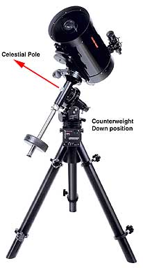
2. Powering up the system 2.1 The Welcome Message As soon as the system is powered up, the welcome message is scrolled through the display. You can make it scroll faster with the RA+ hand controller key or return to the beginning with the RA- key. Either of the DEC keys interrupts it. The content of the welcome message, the system's name, level and version, is stored into the Information buffer and can be scrolled through again after startup. 2.2 Initial Power-up When powering up the unit for the first time after inserting/changing the CR2032 Li battery, you may see the words "CMOS reset" appended to the welcome message. This means that during startup an incorrect checksum was detected and the static memory (SRAM) was reset to its initial values. You should not see this "CMOS reset" again, unless your battery goes low. 2.3 Startup Modes This is the most important chapter to read ! The system is programmed never to complete a 360 degree movement in RA. It will always stay within the safety limits defined for the east and the west side, making a "meridian flip" if necessary. To avoid possible damage to your telescope or mount it is essential that the initial (cold) startup is done in the "counterweight down position" (abbreviated CWD position from here). The CWD is the position the telescope usually has after attaching the optical tube (OTA) to the saddle plate: the counterweight shaft pointing down, the counterweight on its lowest position. In the northern hemisphere, the counterweight shaft must be pointing to the north, similarly, southern hemisphere observers should have the counterweight shaft pointed south. How to change the factory defined safety limits is described in section 4.2.1.7 (Setup->Mount Parameter->Set Safety Limit). The system checks during startup if the telescope was aligned when the power was switched off or lost. If not, it will make a "Cold Start" automatically, otherwise you'll be offered a menu: > "Cold Start" >
The "Cold Start" The system executes the cold start automatically if the telescope was not aligned at power-off. You have to use this startup method if your mount was moved. All volatile internal variables will be set to their initial values. The mount has to be in the CWD position (accurate to within a few degrees, depending upon how physically close to the safety limits you wish to set) The "Warm Start" You may choose this option, if your mount was not moved, but the OTA was. It allows the system to re-use the internally calculated mount modeling parameters. You will have to make a 1-star-align, but after that the modeling will be used immediately. The mount has to be in the CWD position. The "Warm Restart" This is especially useful for permanently mounted telescopes, after a power loss, or for observing at daytime. The Gemini system calculates the (sidereal) time that passed by since power down and knows where it is pointing to. The system starts up aligned, position failures coming from time differences may be corrected later. Since the CWD position is not required here, you are responsible for guaranteeing that the position is correct. If you are in doubt, you should check if the safety limits are correct by carefully slewing to the eastern or western border. If the system does not stop the slew automatically about 10 degrees away from the limits, slew into CWD position, switch the unit off and on and select a "Warm Start" instead. Starting Up in Debug Mode If you have problems with the serial link to your computer or your planetarium software, you can press one of the Handcontroller keys while powering up. Doing this, the unit will work in "Debug Mode" and show all commands that a received from the PC in the Information Buffer. You can scroll through this buffer with the "Show Information" menu item. You should see the commands send by the software (but numerical values omitted), which are ASCII characters, e.g. ":GR#:GD#". If not, the serial link is not operational. "Debug Mode" will be appended
to the welcome message.
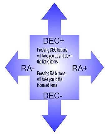
3. Telescope Motion Control After the startup is finished, the system is in Telescope Control Mode. You can move the telescope with the hand paddle. There are three basic speed rates: Guiding Speed (+- 0.2...0.8 of the tracking speed), Centering Speed (up to 255 times the tracking speed) and the Slewing Speed, which can be adjusted separately for manual slewing (with the hand paddle) and the slew perform by the GoTo pointing operation. Holding down a key lets the telescope move. Pushing down the opposite key while moving lets the telescope accelerate to the next speed rate. For your convenience, the handcontroller works in one of three modes: the Visual mode, the Photographic Mode and the All-Speed Mode. You can move both axes simultaneously. The Visual Mode In visual mode, the guiding speed is not available. When you press a key, the telescope moves with Centering Speed. Pushing the opposite key lets the system accelerate to the manual slewing speed. If you are moving both axes, both will speed up. Ramping up and down occurs independently for both axes. This mode is intended for visual observing and for looking up objects. The autoguider port is not active in this mode. The Photographic Mode In this mode the slewing speed is not available. In photographic mode, the centering speed is subdivided in 4 stages to allow easy centering of an object in the field of view or at a CCD chip. Pressing a handcontroller key moves the telescope at the selected Guiding Speed. Pushing the opposite key once will change to 1/8 of centering speed to allow fine centering of the target, then after about 2 seconds speed will increase to 1/4,
If you want to guide a photo manually, you may plug the handcontroller into the autoguider outlet. This way you are sure that you can't move the scope too fast accidentally. As mentioned above, you will not have the handcontroller LED illuminated when plugged into the autoguider outlet. The All-Speed Mode All speeds are available, from Guiding Speed to Slewing Speed, by using the opposite-key trick. You can use this mode e.g. while drift aligning, when you need very fine centering a star at the crosshairs and a fast move from the meridian to the eastern or western horizon. For observing, you'll probably select the visual or photographic mode. You select the mode by means
of the Setup->Hand Controller menu item. Like some other settings, it is
remembered permanently and will be in effect even after powering down and
up again.
4. The Menus 4.1 Entering and Leaving Menu Mode There is only one way to enter the menu mode: shortly pressing the menu key. This key is located at the board to the left of the display. It is illuminated to be found in the dark when the screensaver has blanked the display. In parallel, it is available on the DeLuxe HC. Shortly pressing the menu key toggles between: Telescope Control Mode andToggling the Mode changes the way the HC keys are interpreted. If you press the menu key, you'll see the word "M E N U" in the display. Now you can go through the menu and command the system. Pressing the key again will change back into Telescope Control Mode. A message informing about the actual tracking mode is displayed. There are some commands in the menu that will switch back to Telescope Control Mode without pressing the menu key. These commands are identified by (->TCM) in the reference. New in Level 2: If you press and hold the menu key for at least one second, a selection of Centering Speeds (2x, 8x, 16x, 32x, 64x, 128x) and Hancdontroller Modes (Visual Mode, Photo Mode) scrolls through the display. The item that is displayed at the moment you release the key is selected and the Gemini will be in TCM. 4.2 The Main Menu The Menu Mode always starts with the Main Menu displayed. The number of available menu items depends upon the state of the system. You can scroll through the menu with the hand controller's DEC keys. At minimum, after a cold startup, the following menu items are available: Align TelescopeIf the telescope is aligned (after a warm restart or having done an Initial Align) two additional menu items RA/DEC Coordnt.are displayed. Selecting a database object or transferring object information from a PC gives (if the telescope is aligned) two other menu items, extending the Main Menu to the final size Align Telescope4.2.1 Setup Normally, this is the last
menu item, but in the beginning you will want to start with it. All data
entered here are stored in the battery backuped SRAM, together with a checksum.
If the checksum is wrong at powering up, all values default to standards
settings and a "CMOS reset" message is displayed. The Setup menu contains
the most submenus. Here's an overview, indented according to the menu level:
4.2.1.1 Setup->Hand Controller There are three choices: Visual mode: pressing one key moves the telescope with centering speed, pressing the opposite one accelerates to slewing speed. Photographic mode: the keys are used for guiding, pressing the opposite key switched to centering speed. If you are guiding manually, you can select this mode and thereafter connect the hand controller to the Autoguider port to avoid speeding up. All speed mode: all three speeds are available. You can accelerate to slewing speed by pressing the opposite key twice with a short break in between. All choices will leave Menu Mode and will switch to Telescope Control Mode (->TCM). Training PEC will switch to Photo Mode. 4.2.1.2 Setup->Mount Parameters 4.2.1.2.1 Setup->Mount Parameter->Tracking Speed SiderealSelects one this tracking speeds and exits to TCM. While sidereal and solar speeds are very exact, lunar has to be an average speed because of the moon's non-circular orbit. The King rate The King rate takes refraction into account and adapts the tracking rate to the speed the apparent place of an object changes. King rate tracking will therefore be a bit slower than sidereal tracking. Of course refraction will change the object's apparent declination too. This could be guided out, but taking long exposed wide-field shots this way will show differential refraction: the objects nearer to the horizon will move with another rate (in RA and DEC) than objects higher in the sky, where the refraction angle is smaller. Here the second part of King tracking comes into account: the questions is: where is the RA axis pointing to? The answer seems simple: the axis should be parallel to the north-south axis the earth is spinning around. Alas, the only places where it is that simple are the poles. At all other places, the refracted pole, the place where you (and your polar alignment scope) see the pole (and Polaris for the northern hemisphere), will be lifted slightly up towards the zenith, giving the refracted pole the same azimuth, but a higher elevation than the true pole. The difference will be 1 to 2 arc minutes in middle latitudes, increasing fast at low latitudes to about 34 arc minutes at the equator. Alas, that's not the end of the story. Aligning the polar axis to the refracted pole will allow to properly photograph the area around the pole. At the meridian, with targets relatively low above the horizon, the objects will have a non-circular trajectory. King's method is to adjust the polar axis not to the true pole, but a certain amount higher towards the zenith. This way the apparent trajectory is approximated by the circle around the slightly shifted polar axis. By the way, if you are using objects with about the declination of the target you want to photograph for drift aligning, you'll not align to the true pole but, the way King proposed, to a point defined by the declination used and your observing site's latitude. Using the King rate for tracking is best combined with this kind of drift aligning. The system contains two different implementations of the King rate: Level I uses a static rate, 0.3 per cent slower than sidereal, giving a good estimate of the drive rate needed when photographic a target near the meridian and about 30 degrees above the horizon at middle latitudes. Higher software levels uses a adaptive King rate speed, which is adapted in realtime in accordance to the position the telescope points to. 4.2.1.3 Setup->Mount Parameter->Moving Speeds Used for defining the speeds forWhile the guiding occurs at constant speed in DEC, in is overlayed the tracking speed in RA. The standard Guiding Speed is 0.5x, giving 0.5x and 1.5x tracking speed in RA respectively. The highest guiding speed is 0.8x, giving approximately 0.8x tracking speed in DEC, 0.2x respectively 1.8x in RA.Guiding (0.2...0.8), counted +/- to the tracking speed. 4.2.1.4 Setup->Mount Parameter->TVC Value This point lets you select a value between 0 and 255. This is the number of steps which are made at high speed whenever changing directions in DEC. The TVC can eliminate the hysteresis when changing the directions in DEC. The TVC is only active while in Photographic Mode. You should choose a value that results in a short or no delay when changing the guiding directions in DEC. If you see a short jump, you have to decrease the value. 4.2.1.5 Setup->Mount Parameter->PEC Train PECThe Periodic Error Control helps to eliminate the periodic error caused by the very slight helical path variation in the shape of the RA worm. You experience these as changes in the tracking speed, causing a star?s position to periodically move a few arc seconds forward or backward while the worm gear turns. The period is defined by the time one worm revolution takes: about 4 minutes for the G-11, HGM-200 and MI-250, about 8 minutes for the GM-8 and CI-700. As long as PEC isn't trained, the only menu item that appears here is "Train PEC". You only should select this if you are ready to train PEC, having a star centered in a eyepiece reticle. If you select it, a counter is shown on the display, counting down from 240 to 0 for the G-11/HGM-200/MI-250 setting and 480 to 0 for the GM-8 or CI-700 setting. A beep informs you if the training phase is finished. Please note, that these numbers are not exactly seconds. If you are, for example, guiding forwards, one revolution of the worm will be completed earlier. Of course, this should average out with the guiding backwards normally. With trained and stored PEC, you can choose other options: switch PEC usage off or on, or clear the PEC data. 4.2.1.6 Setup->Mount Parameter->Mount Type If there are different mount types supported by your system, you may select it here. Step sizes and directions will be set. 4.2.1.7 Setup->Mount Parameter->Set Safety Limit The system will never make a complete turn in RA. There are default limits set how far the RA axis can be turned to the East and to the West. If the mount cannot reach its target, it has to make a meridian flip. If you want to change the limits, you can set them in with this menu item. You have to start up the system accurately in CWD-position and slew to position you want to set as the new limit. While this is no problem if you are narrowing down the allowed range, going beyond the old limits is a bit tricky. About 10 degree before you reach the old limit set, the system will softly ramp down the speed until the motor stops near to the real limit. Go carefully on moving with centering speed or slewing slowly until the systems stops the motor and you hear the buzzer. Now you are outside the allowed range and the buzzer won't stop until you go back inside the allowed range or set the new limit with this menu item. IMPORTANT NOTICE: The limits are stored in CMOS SRAM. Whenever the "CMOS reset" message is displayed during startup, all values are reset to the factory default. If you need different limits to be set, you have to set them in again! 4.2.2 Setup->Encoder EncRes RAWith the first two menu options you can define the axial encoder resolutions. RA and DEC encoders may have different settings. Up to 32768 ticks/revolution are allowed. In general, the sign is a plus (+) if the encoders are moved in the same directions as the axes and minus if the direction is reversed by a gear. Setting up the encoders wrongly will result in a unwanted behaviour of the system. You will see the characters 'R' or 'D' displayed at the right side of the display, indicating a correction to the internal addresses caused by and derived from the encoder data. The Test Encoder menu item displays the actual values of both encoders. It can be used for testing, if you are connecting your encoders the first time. One revolution of an axis should bring the counter back to the same value. This is easily tested for DEC, but for RA you can only move between the mechanical limits. This is one of the menu items that changes the status from Menu back to Telescope Control Mode (TCM). Selecting Setup->Encoder->Ignore Encoder prevents the encoder from being used by the software without physically disconnecting them. Setup->Encoder->Use Encoder sets them online again. 4.2.3 Setup->Set Alarm Timer Alarm OnThe time for sounding the alarm (or closing a camera's shutter) is stored in the real time clock (RTC). The RTC has to be running UTC. The alarm time has to be set in UTC too. Albeit the alarm time is stored permanently in the RTC, the alarm is always off after powering up. You can activate it by setting the alarm time or using the "Alarm On" menu item. "Alarm Off" will disable sounding the alarm. 4.2.4 Setup->Set Date/UTC Sets the date and time in the real time clock chip RTC. The format is yymm.dd hh:mm:ss. As mentioned above, the clock must be set to UTC to allow for the astronomical calculations. 4.2.5 Setup->Credit Info Displays software version, copyright and credit information as a scroll-text. Displaying the scroll-text works the same way as described for the Show Information menu item. 4.2.6 Setup->Restore Defaults Selecting this menu item restores the factory defaults into the CMOS SRAM. You can choose between the standard values for Losmandy HGM or Mountain Instruments (new in Level 2). All additional data are deleted or initialized too! 4.2.7 Setup->Dim Display 100% BrightnessSelects the brightness of the display. The 100% are very bright and should only be used in bright sunshine. 6.6% are adequate for the night and keeping dark adaptation. 4.2.8 Setup->Geographic Location LongitudeShows and let you set the selected Longitude, Latitude and Timezone of the Observation Site. It is important to set Longitude and Latitude to about the correct values of the observing site, because this information is used to calculate the height of objects above the horizon. Slews to objects below the horizon will be rejected. The longitude is counted from Greenwich, eastern longitudes have a 'E', western longitudes (including the American continent) have a 'W' sign. From the sign of the Latitude the program knows the hemisphere, northern latitudes have a positive, southern a negative sign. Users on the southern hemisphere should set their longitude and latitude first. The tracking direction in RA depends on the sign of the latitude. 4.3 Align Telescope The following options can be selected to align the Gemini system.
Bright star list OTA at Eastside Bright star list Bright star list After a Cold Start or a Warm Start the Gemini system is in Telescope Control Mode. The telescope can be moved by slewing with the hand controller or, in case encoders are connected, manually, until a known object is centered in the FOV of the eyepiece. In this not aligned state, the telescope only knows the position angle of the RA axis (from the CWD-position), but not the exact position where it is pointing. All points of the menu that require the mount to be aligned are disabled. PC address requests are answered with the position of the (north or south) pole after startup. The initial alignment gives two important pieces of data to the system. First, you tell the system to which coordinate it is actually pointing. As a submenu of Initial Alignment there is a list of bright stars available, stored with sub-arcsecond accuracy. If you have selected a database object, its name is shown first, before the list of stars. The database objects coordinates are stored rounded to 20 arc second accuracy, the failure should be at maximum 10 arcsec, well suited for aligning. Solar Systems objects only have accuracies in the magnitude of a few arc minutes and should not be used for alignment if possible. The alignment star list contains 25 stars of both hemispheres. Only the stars above the horizon are shown. All coordinates are precessed to the equinox of the date and corrected for refraction. Alignment is possible with objects on both sides of the meridian. A German Equatorial mount can point to the same object in two ways. The system therefore asks you the position of the Optical Tube Assembly: "OTA at Westside" or "OTA at Eastside". The position of the OTA is important, not that of the object pointed to (which is known by the system)! It is not important if the OTA is a little bit east or west of the meridian - the OTA is at the Westside if it can point from the east to the meridian without doing a meridian flip and vice versa for the Eastside. The star selected for Initial Alignment is remembered by the system and is (if above the horizon) offered again the next time you select this menu item. After you have aligned the telescope, you can use planetarium software to control it. Doing an Initial Alignment initializes all internal modeling variables - it is a 1-star align. Already done additional alignments are reset. This can be helpful if you made an erroneous Additional Alignment. There is one exception: if you selected a Warm Restart on startup, the telescope will immediately be aligned. The accuracy of the alignment depends upon that of the RTC clock. Every second the clock is running too slow or too fast since the last shutdown (only the difference matters, not the absolute value) will give 15 arcsec deviation. Because of this, the first Initial Alignment after startup does only a Realign, correcting the position without resetting the internal variables. This realignment can be used if you want to synchronize the system to the correct location: switch the system off an on, select an object or bright star, center it and select "Initial Align" to do a realignment. Please note: using Polaris for the Initial/Additional alignments is not a good idea, because even small sighting errors can cause very large RA value changes near the pole. 4.3.2 Align Telescope->Additional Alignment The pointing accuracy of the telescope after a the Initial 1-Star-Align will depend strongly upon precise polar alignment, mount axes' perpendicularities, the East/West optical/mechanical axis parallelism, flexure and bearing play, gear play and mirror flop. Usually imprecise polar axis alignment results in the biggest deviations. The software is partially modeling this and calculates corrected positions for the GoTo operation. The Additional Alignment menu item gives the system data about deviations between the expected and the real location of an object. To use this menu item you have to center a known object (from the star list, the databases or selected by the PC) in the eyepiece first, normally after having done a GoTo operation. By doing the Additional Alignment, the locations' difference is used to calculate parameters for the systems internal mount model. After the Initial Alignment the first two Additional Aligns are used for an estimate of the polar axis alignment. Just select an object, let the telescope point to it, center the object and select additional align. Do this with some objects significantly far away from the first alignment object and from each other in RA (hour angle) as well as in DEC to give a good base to determine the values, but without having the telescope to make a meridian flip. The system will reject objects with the message "Sorry. Rejected." if one of the internal calculated determinants will be near to zero. If that happens, please choose another alignment object. After each Additional Align, the values of the polar axis deviation in azimuth and elevation are displayed in arc minutes. If you do more additional
aligns, the model parameter for non-perpendicularities are calculated.
If you've made an erronous alignment, you may have to delete all the modelling parameters info by doing a Initial Alignment again. The first Additional Align at the opposite side of the meridian (after a meridian flip) will be used to set a reference point at this side and to calculate the gear play and mirror flop values (FR in RA and FD in DEC). Subsequent additional aligns at this opposite side will be used for further refinements of the model. Up to 254 Additional Aligns at each side of the meridian could be done. For the model used in Level I, about 10 alignments should give good pointing accuracy. For best pointing accuracy, we recommend: You can test the effect of the modeling by using the Guide-> menu item. Unlike the GoTo, the Guide-> menu item always shows the (precessed and refraction corrected) object coordinates without the corrections calculated by the pointing model. It points to the coordinates where the telescope would point after the initial 1-star-align without any additional alignments. If the modeling should give bad results, you can reset the parameters by doing an Initial Align and repeat the procedure. 4.3.3 Align Telescope->Synchronize
(new in Level 2)
The Synchronize function shifts the internal coordinate system to reflect
the exact position of the selected object. In contrast to the Additional Alignment,
the main modelling parameters are not changed, only the Index values (IH and ID)
are recalculated to reflect the new position. As long as the modelling is not
active, the Synchronize works similiar to an Initial Alignment.
The Synchronize can be used f.i.
4.3.4 Align Telescope->Polar
Align Assist
After the Initial Alignment,
the mount knows where it is pointing to and offers this additional menu
item. It instructs the mount to slew between two stars of the internal
alignment star list you have to select. Normally, the first star offered
is the alignment star you have chosen and the second is Polaris (this is
the reason why Polaris is part of the list). But you can scroll through
the Bright Stars menus and select other combination. The system will remember
the stars that were chosen for alignment and use the as first value for
subsequent alignments. When the OTA is pointed to the target, you are informed
and can center it with the azimuth and elevation knobs.
You can also use the HC for
additional corrections. Pressing the menu key lets the telescope slew to
the other star to repeat the procedure. The procedure is interrupted by
pressing one of the hand controller keys while slewing.
4.4 Object Databases
Credits
In general, the whole astronomical
community has to be credited to collect, check, sort and provide this great
amount of data. Special credits are due to Wolfgang Steinicke for long
years of work checking the NGC and IC catalogs and correcting many bugs
and errors. If there are errors in converting his data into the internal
databases they are caused by the system's developer.
Accuracy
With the exception of the
Solar System objects, all coordinates are stored rounded to 20 arcsec,
giving 10 arcsec accuracy for the standard epoch J2000.0. The coordinates
are precessed to the equinox of the day when the object is selected. Nutation
is neglected. The apparent place is calculated, taking refraction (for
standard air pressure and temperature) into account. For the moon, the
topocentric coordinates are calculated.
Object Information
After selection, the object
name is displayed, together with the hour angle in minutes (negative if
east of meridian) and Declination in degrees. This can be used for planning
photo sessions.
The permanently stored additional
data depend upon the catalog and object type. Mutual cross references,
constellation, common name, type, magnitude, size are shown for the Messier,
NGC and IC catalog. Type and size are provided for the Sharpless2 catalog.
No further data are available for solar system objects, but constellation,
sometimes Greek letter designation, type, magnitude and spectral class
for the bright stars. SAO stars have only their magnitude stored, double
stars are marked by a 'D'.
Included Databases:
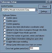
From the Washington Double Star catalog WDS a selection of 3989 star systems fitting the following criteria is available: magnitude of primary star < 7m2, magnitude of second component <14m5, separation > 0.4 arcsec. The 1143 Planetary Nebulae of the Strasbourg/ESO Galactic Planetary Objects catalog GPN, including most objects of the PK (Perek, Kohoutek) catalog and the WDS have coordinate information as designation. After selection of the first coordinate an appropriate entry is displayed and scrolling through the database with the DEC buttons allows to choose the object. The User Defined Catalog "User Def. (n)" selection, with n equal to the number of objects in this catalog, is only displayed if there were objects downloaded into Gemini's SRAM over the serial interface, f.i. with the Windows (R) Gemini Control program. 4000+ objects can be stored into this catalog. After selection of an object using the number the stored name is displayed and scrolling through the catalog is possible again. The identificator of Messier, NGC and IC catalogs can be selected without the leading zeros, if you don't want the extension characters for NGC and IC to be selectable. The character "->" serves as "Enter", to abbreviate the selection. 4.5 Show Information Allows to scroll through the information buffer. RA+ speeds scrolling up RA- sets back to the beginning if pressed alone or stops scrolling if pressed after RA+. DEC+ and DEC- interrupt the scrolling, going to the adjacent main menu selections. After powering up, the information buffer contains the welcome message, later additional status information. It will receive object data after selecting an item from the databases, mount modeling parameters after a Additional Alignment or Synchronize and debug information, if the board is in Debug Mode (powered up with a key of the hand controller pressed). In debug mode, the commands received from a connected PC without the numeric parameters are stored. 4.6 GoTo <object_name> This menu items only appears if you have selected a database object, one was transferred from the PC or found by Identify, and the telescope is aligned. Slews to objects below the horizon will be rejected. Pressing any of the had controller keys interrupts the Slew. 4.7 Guide-> <object_name> This menu items only appears if you have selected a database object, one was transferred from the PC or found by Identify, and the telescope is aligned. This menu shows the difference between the actual telescope position and the location of the selected object. You can move the telescope manual (if you have encoders) and/or using the hand controller until you get all zeros. Selecting this menu item switches you back to Telescope Control Mode. The Display Saver is off. GuideTo shows the distance to the un-modeled position of the object, informing you what deviations were calculated by the model after a Goto. 4.8 RA/DEC Coordinates RA/DEC DisplayAppears only if the telescope is aligned. 4.8.1 RA/DEC Coordnt.->RA/DEC Display Shows the actual position. The hand controller is switched into TCM. The screen saver is off. 4.8.2 RA/DEC Coordnt.->Enter RA/DEC Shows the actual position and allows you to change the coordinates. To enter a new position, go through the display with the RA buttons and change with the DEC buttons. After you have left the last number on the display (DEC seconds) with the RA+ button, the coordinate given will be stored as "selected object" and can be used for GoTo or GuideTo, if they are above the horizon. Elevation and hour angle are displayed. 4.9 Identify This main menu item appears only if the telescope is aligned. You can select objects from a subset of the database catalogs, specifying a combination of type and brightness. The up to 10 most nearby objects in a range about 10 degrees around the actual telescope position will be stored. The most nearby object and its distance are shown first. You can scroll through the list with the DEC keys. The last object shown on the display will be stored as the "Selected Object" with coordinates and data available. You have two options: the RA+ button will activate the GoTo and will slew to the object shown. The RA- will leave back to the Identify menu item, but with the last object still being selected for Object Info, Guide To or GoTo. 4.10 Object Search Moves the telescope in alternating, increasing moves in RA, DEC around the actual position. You have to select a field of view (FOV) between 5 arcmin and 2 degrees. The distance between the lines the telescope is moving will be FOV/sqrt(2) 4.11 Date, Time Select this menu item to display the date and/or time stored in the Real Time Clock (RTC) of the Gemini system. Options available are: 5. Using Planetarium Software Just connect the RS232C cabling, select the "Gemini" setting/driver or "LX200 protocol" if not available, and you are ready to establish the telescope link. Initializing the system setting with The Sky Planetarium Software:
You may also use the The Sky's Telescope->Options->Initialize menu for setting up date, time, and location of your observing site. All values will be set permanently and stored into SRAM and/or RTC. It is best to use the items from bottom to top. Begin with setting the time zone, because it will be needed for the other settings, since the system's internal clock runs UTC. After the time zone set the time, and lastly, the date. There is a modest delay while PC software reads out and confirms the newly set date. Make sure your telescope
is aligned. After alignment, the system may be controlled by the planetarium
software.
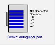
6. Troubleshooting The Buzzer sounds Once you reach the eastern or western limit, either by slewing or by tracking, a hard stop will occur and the buzzer will sound. You can get out of the "stop" condition by moving into the allowed range or setting the safety limit. Please look at the Setup->Safety Limits paragraph for more information. Tracking will be stopped as long as the mount is outside the allow range. At the western limit, you have to go some degrees off the limit into the allowed range to allow for tracking before the buzzer is quiet again. Long Centering phase during a GoTo operation See "The Buzzer sounds". The telescope may have to be positioned within some degrees of the eastern/western RA limit. For safety, the fast slew is braked and the RA axis has to be moved the last few degrees at centering speed. You can stop the GoTo operation by pressing any key of the hand controller. Selecting GoTo starts slewing again. Inaccurate position after a Warm Restart The Gemini systems internal real time clock (RTC) is as accurate as most PC clocks, hence will drift up to a few minutes in a month. It is this time that is used to establish the RA position of an object, with 4 seconds in time being equivalent to one arc minute in position error at the meridian. You can reset the RTC very accurately by using the PC RS232 link and having your PC?s time updated by the Internet, just prior to doing an observing run. Motor STALLED (R)(D) There may be three reasons for this: a motor isn't connected correctly to the board and the systems doesn't get back motor encoder values when it tries to move, the slewing speed is too high and has to be decreased in Setup, a mechanical problem exists. Normally, the alignment of the mount should not be lost if a stall occurs. If a stall is signaled, the position is reset to the place the motors point to. A manual slew or a GoTo operation will be interrupted. "Tracking STOPPED" message A RA motor stall occured while tracking. The RA motor is not connected, a cable problem exists or too much torque is needed because the worm gear mesh is too tight or the RA clutch isn't tightened the way it was during adjusting the gear mesh. Tracking is stopped until a HC key is pressed in TCM. "CMOS reset" message upon startup or incorrect date/time The CR2032 Li battery was exchanged or is low. If the problem persists, contact your dealer. Serial Communication problems Please check the layout of the serial cable and of the serial communication port of your PC first. Check if you have bridged the modem control lines as necessary. If you want to see if PC commands arrive at the board, you can start up in "Debug mode" by pressing any key of the hand controller and check for incoming transmissions with the "Show Information" main menu item. If you are using a PC with a fast CPU and buffered serial I/O circuitry, the microcontroller of the Gemini system may not be able to receive and store all characters in time. Check the setting of the communication port of your PC and disable the 16550A serial controllers FIFO. You can try to use a smaller FIFO send buffer first. APPENDIX A - Technical Data Power: 12-18 Volts DC 3 Amps Temperature range: -5 to 35° C APPENDIX B - Autoguider Port
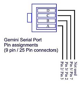
The Gemini Autoguider port is plug compatible with SBIG model ST4, STV autoguiders. SBIG ST237/ST7/ST8/ST9 cameras with TTL outputs must be connected using the SBIG relay box, the optional Losmandy Optocoupler or equivalent. APPENDIX C - Serial Communication
A graphical representation of the Gemini Serial socket is pictured left (i.e. Pin D is closest to the top of the Gemini main Panel) Either a DB9 or DB25 connector
can be used for serial communications to a PC.
NC= Not connected
|